This mini acoustic chamber is designed and constructed using low-cost materials from local hardware/material stores. The goals/usages of the chamber are:
- Providing a flexible and portable environment with consistent frequency response accuracy and control of experimental stimulus and measurement
- Preventing hearing damage in conducting small-scale acoustic-related experiments
- Testing and characterizing small-scale sound or audio setups (typically 10-inch, or smaller, speakers)
- Performing controlled small-scale acoustic experiments
- Performing controlled bioacoustic experiments
Dimensions
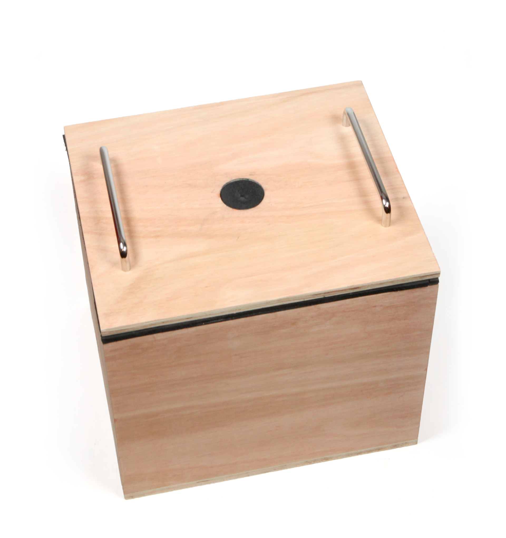
The inner dimensions of the chamber are 23.6 cm (l) x 19.3 cm (w) x 16.6 cm (h). The net volume of the chamber is 7,561 cm3. The chamber is semi-airtight and the two handles on the top cover can be used to lift open to top cover. The round hole in the center of the top cover is made to access the chamber for measurement (e.g., microphone) or observation instrument (e.g., digital microscope).
Volume of the chamber
According to the ISO 3745, for a full anechoic chamber, the volume of the specimen for measurement should be 5% of the net volume of the chamber:
\(V{specimen} \leq 0.05 \cdot V{chamber}\)
The gross volume of our chamber is:
\(V{gross} = 33.1 \times 28.8 \times 26.1 = 24,880.6 cm^3\)
The total thickness of one side of the wall materials is 9.7 cm (Table 1). The net volume of the chamber is then:
\(V{net} = 23.6 \times 19.3 \times 16.6 = 7,561 cm^3\)
For example, in a bioacoustic experiment using cell cultures, the volume of a typical 60 mm cell culture dish is (radius= 3 cm, height= 1.6 cm):
\(V{60mm} = \pi r^2 \cdot h = 45.2 cm^3\)
The requirement is then satisfied since:
\(V{60mm} < 0.05 \cdot V{net}\)
Materials
The following materials are used to construct the chamber:
| Material | Thickness (cm) |
|---|---|
| Birch plywood | 2.2 |
| Rockwool | 2 |
| Felt | 0.5 |
| Acoustic foam | 5 |
| Total thickness |
9.7 |

Construction of the chamber

How the chamber is constructed:
- Plywood was cut to size using a CNC milling machine.
- Plywood pieces were glued using standard wood glue. The pieces were tightened with clutch clamps and left at room temperature over a night. Then silicone was applied along the edges inside the chamber.
- Rockwool and felt were cut and glued using a spray adhesive.
- Soft/porous materials (Rockwool + felt + wedge foam) are glued inside the chamber.
- A rubber material was cut to fit in the hole of the top cover. This is made to access inside the chamber with a calibration microphone or digital microscope/camera for measurement and observation.
.png)
Characterization of the chamber
For the characterization of the chamber, a logarithmic sine sweep between and 22,000 Hz and a basic sound insulation test (dB SPL comparison) was performed using white
noise which played for about 20 seconds each time. A simple setup (Figure 5) with a laptop (free software Room EQ Wizard (REW) version 5.19) and a soundcard (Behringer 11 UMC404) was used with an omnidirectional calibration microphone (EarthworksM50). The sound source was varied between different types of speakers for comparisons.

The measurement
Three different types of speakers (sound source) were used for comparison:
- Sound source A: Surface transducer coupled with 60 mm cell culture dish
- Sound source B: 2-way 10-inch coaxial speaker
- Sound source C: Active 2-way studio speaker (Genelec 8020b), used for sound insulation test placed outside the chamber
The measurements were taken in the following order.
Measurement 1: Characterisation of the sound sources using a sine sweep in an open room (Figure 6)

Firstly, we characterize sound sources A and B which are the types of speakers that the chamber is designed for.
Measurement 2: Characterisation of the chamber using a sine sweep (Figure 7)

Then, we characterised the chamber using the sine sweep:
- The sound source A and B were used.
- The position of the sound sources and the calibration microphone stayed the same inside the chamber.
- The measurement was taken under two different conditions:
1. The top cover of the chamber opened.
2. The top cover closed.
Measurement 3: White noise measurement in terms of dB SPL
We also tested the chamber for sound insulation efficiency using sound sources B and C:
- The measurement was taken with the top cover closed under two different conditions:
1. The calibration microphone inside the chamber.
2. The calibration microphone outside the chamber 30 cm away. - The position of the sound sources stayed the same inside the chamber.
Measurement 4: White noise measurement in terms of dB SPL using a studio speaker (Figure 8)

Lastly, the sound insulation test was performed using the sound source C:
- The measurement was taken under three different conditions:
1. The sound source and the calibration microphone in an open room.
2. The calibration microphone inside the chamber with the top cover opened and the sound source was outside the chamber 30 cm away.
3. The same condition as the second condition but with the top cover closed.
The modes of the chamber
A distribution of modes is crucial to avoid any heavy concentration of energy. An ideal situation would be to have irregular construction but as mentioned previously it is not easy to build. Using the inner dimensions and the ratio (Table 1) of the chamber, the ˇ°Bolt-areaˇ± has been tested (Figure 9). As illustrated in Figure 4, the chamber is within the so-called "the safe zone" and the modes are likely to be distributed more evenly than if the proportion of the chamber fell outside of the Bolt-area zone.

In a square-shaped space, a room mode can be defined:
\(f = \frac{v}{2} \sqrt{(\frac{l}{x})^2 + (\frac{m}{y})^2 + (\frac{n}{z})^2}\)
where l, m, n are positive integers that cannot be all 0. As a reference, here are the first five modes of the chamber:
|
# |
Frequency |
l-m-n |
|---|---|---|
|
1 |
732.91 |
1-0-0 |
|
2 |
897.91 |
0-1-0 |
|
3 |
1045.73 |
0-0-1 |
|
4 |
1159.05 |
1-1-0 |
|
5 |
1276.99 |
1-0-1 |
The cost of the chamber
As we aimed to construct a cost-effective chamber, we used materials that are relatively easy to find at local hardware and material stores at a minimal cost. The CNC milling machine was used at a maker space that is open and free to the public with an optional inexpensive monthly membership fee.
|
Material |
Cost (NOK) |
|
Plywood (red temp) |
335 / m2 |
|
Rockwool |
57 / m2 |
|
Felt |
80 / m2 |
|
Acoustic foam |
588 / m2 |
| Spray adhesive |
300 |
| Other tools |
300 |
|
Total |
1 660 |
The total cost is about 190 USD (checked on 10 September 2021) whereas a commercially available anechoic chamber may cost above 15,000 USD (prices for new and used anechoic chambers checked on ebay.com and alibaba.com).